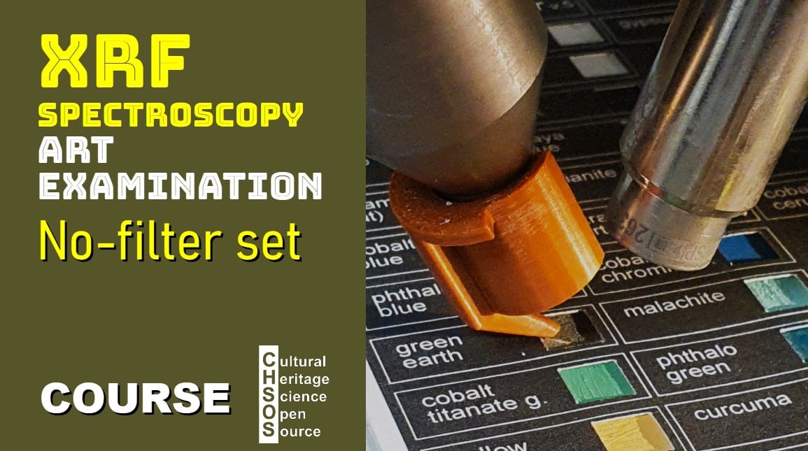
- Understand the function and benefits of the no-filter setup in XRF spectroscopy.
- Identify the types of elements best analyzed using the no-filter setup, specifically those with low-energy XRF lines.
- Differentiate between the routine, LOW-KEV, and no-filter setups for XRF analysis.
- Practice applying the no-filter setup to identify low-energy elements in a sample.
- High-density polyethylene (HDPE) plate
- Samples for analysis, specifically containing elements such as silicon and magnesium
- Pigments Checker, specifically green earth, containing minerals such as celadonite and glauconite, silicate minerals
- Review the purpose of filter sets in XRF spectroscopy and their specific roles.
- Summarize the ROUTINE filter set for general analysis and the LOW-KEV filter set for focusing on XRF lines below 10 keV.
- Introduce the no-filter setup as a specialized approach for very low-energy XRF lines, highlighting its strengths and limitations.
- Describe the no-filter setup: settings are 10 kV and 10 µA, with no filter added.
- Explain how the no-filter setup enables the capture of low-energy lines below 2.5 keV, making it suitable for detecting elements from magnesium up to sulfur.
- Emphasize that this setup is optimized for elements with lower atomic numbers.
- Set up the HDPE plate as a target to reflect the X-rays from the tube, allowing the detector to capture the tube’s output at both high and low settings (50 kV/50 µA and 10 kV/10 µA).
- Compare spectra produced by the no-filter configuration at different settings and note the absence of high-energy X-rays at 10 kV.
- Discuss the flat, undisturbed spectrum observed below 2.5 keV and its advantages for low-energy XRF line analysis.
- Explain that green earth, a pigment containing celadonite and glauconite (iron-rich silicate minerals), is an ideal test sample for low-energy analysis.
- Conduct a comparison of the green earth pigment using both the LOW-KEV and no-filter setups, observing the resulting spectra.
- Note the silicon peak at 1.7 keV that appears only in the no-filter setup, verifying the presence of silica and confirming the silicate composition of the pigment.


To reinforce the concepts discussed here, we also provide a video lesson that visually walks through the key points of this topic. Watching the video alongside the text can help you better understand and apply these ideas in practice.
The course XRF Spectroscopy for Art Examination introduces conservators, art historians, and scientists with interest in Art to the principles and practical applications of X-ray fluorescence (XRF) spectroscopy in the examination of artworks. The course starts with basic principles of XRF and gradually explores its role in identifying materials and methods used in the creation and conservation of art.
Course Objectives
- Understand the fundamentals of XRF spectroscopy and how it applies to the analysis of art.
- Learn the key features and limitations of XRF for examining art and archaeology.
- Gain skills in interpreting XRF spectra to identify specific elements in paint layers, inks and metals.
Scientific Art Examination – Resources:
Getty Conservation Institute (GCI) – USA
The British Museum – Scientific Research Department – UK
Scientific Research Department – The Metropolitan Museum of Art, New York, USA
C2RMF (Centre de Recherche et de Restauration des Musées de France) – France
Rijksmuseum – Science Department – Netherlands


